SAE Flange Pattern Specifications – Dimensions, Bolt Sizes, and Mounting Standard
What is an SAE Flange?
SAE (Society of Automotive Engineers) four-bolt flanges are the industry-standard connection method for high-pressure hydraulic lines. They provide a leak-free, high-integrity face seal using a split or one-piece flange clamp, an O-ring, and four mounting bolts — delivering far superior vibration resistance compared to threaded connections at equivalent pressures.
Winner Cartridge Valves are designed to work seamlessly with SAE Code 61 and Code 62 flange patterns. Selecting the correct code — and the correct mounting dimensions — is critical to system reliability and pressure rating.
Code 61 vs Code 62 — What's the difference?
※ Important Note
Code 61 and Code 62 flanges are NOT interchangeable. Although the nominal pipe sizes overlap, the bolt hole patterns, bolt circle diameters, and overall flange dimensions differ between the two codes. Always confirm the code before ordering.
Maximum Recommended Working Pressure
Four-Bolt Flange Pattern Dimensions
The following table lists key bolt pattern dimensions (in mm) for both SAE Code 61 and Code 62 across all standard nominal sizes. Dimensions A through F refer to the standard four-bolt pattern geometry.
Mounting Hole Specifications
Both inch (UNC) and metric (ISO) mounting configurations are supported. The table below covers the inch mounting specifications per J518.
For metric mounting (DIN 2066), equivalent M8 through M20 ISO threads are used. Please refer to Winner's metric mounting dimension table for exact specifications.
Metric Mounting Threads (DIN 2066)
Selection Guide for Winner Cartridge Valves
Step-by-step
1. Determine your system's operating pressure. If it exceeds 210 bar on the smaller sizes, Code 62 is required.
2. Confirm nominal pipe size (1/2″ to 2″) matching your hydraulic line.
3. Choose inch (J518/UNC) or metric (DIN 2066/ISO) mounting threads based on your manifold or port block material and standard.
4. Verify the bolt pattern dimensions (A–F) against your manifold drawing before finalising the order.
Winner Cartridge Valves are manufactured to precise tolerances and fully compliant with SAE J518 and DIN 2066 standards — ensuring drop-in compatibility with existing hydraulic assemblies worldwide.
Need a custom spec or OEM support? Contact Winner↗
SAE Flange Pattern Specifications — Code 61 & Code 62
SAE (Society of Automotive Engineers) four-bolt flanges are the industry-standard connection method for high-pressure hydraulic lines. They provide a leak-free, high-integrity face seal using a split or one-piece flange clamp, an O-ring, and four mounting bolts — delivering far superior vibration resistance compared to threaded connections at equivalent pressures.
Winner Cartridge Valves are designed to work seamlessly with SAE Code 61 and Code 62 flange patterns. Selecting the correct code — and the correct mounting dimensions — is critical to system reliability and pressure rating.
Code 61 vs Code 62 — What's the difference?
| SAE CODE 61 | SAE CODE 62 | ||
| Standard Pressure Series | High Pressure Series | ||
| Max working pressure | 210 – 420 bar | Max working pressure | 350 – 420 bar |
| Flange sizes | 1/2″ – 2″ | Flange sizes | 1/2″ – 2″ |
| Standard ref. | J518 / DIN 2066 | Standard ref. | J518 / DIN 2066 |
| Typical use | General hydraulics | Typical use | High-pressure systems |
※ Important Note
Code 61 and Code 62 flanges are NOT interchangeable. Although the nominal pipe sizes overlap, the bolt hole patterns, bolt circle diameters, and overall flange dimensions differ between the two codes. Always confirm the code before ordering.
Maximum Recommended Working Pressure
| Nominal Size | Code 61 Maximum Pressure | Code 62 Maximum Pressure |
| 1/2" | 350 bar | 420 bar |
| 3/4" | 350 bar | 420 bar |
| 1" | 350 bar | 420 bar |
| 1-1/4" | 280 bar | 420 bar |
| 1-1/2" | 210 bar | 420 bar |
| 2" | 210 bar | 420 bar |
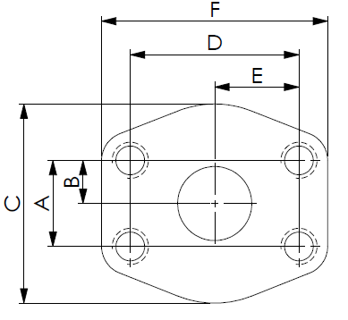
Four-Bolt Flange Pattern Dimensions
The following table lists key bolt pattern dimensions (in mm) for both SAE Code 61 and Code 62 across all standard nominal sizes. Dimensions A through F refer to the standard four-bolt pattern geometry.
| SAE Flange | A (mm) | B (mm) | C (mm) | D (mm) | E (mm) | F (mm) |
| Code 61 | ||||||
| 1/2" | 17.5 | 8.8 | 46.0 | 38.1 | 19.1 | 54.0 |
| 3/4" | 22.2 | 11.1 | 52.4 | 47.6 | 23.8 | 65.1 |
| 1" | 26.2 | 13.1 | 58.7 | 52.4 | 26.2 | 69.9 |
| 1-1/4" | 30.2 | 15.1 | 73.0 | 58.7 | 29.4 | 79.4 |
| 1-1/2" | 35.7 | 17.9 | 82.6 | 69.9 | 34.9 | 93.7 |
| 2" | 42.9 | 21.4 | 96.8 | 77.8 | 38.9 | 101.6 |
| Code 62 | ||||||
| 1/2" | 18.3 | 9.1 | 49.3 | 40.5 | 20.2 | 58.5 |
| 3/4" | 23.8 | 11.9 | 63.5 | 50.8 | 25.4 | 75.0 |
| 1" | 27.8 | 13.9 | 69.9 | 57.2 | 28.6 | 81.1 |
| 1-1/4" | 31.8 | 15.9 | 77.8 | 66.7 | 33.3 | 95.3 |
| 1-1/2" | 36.5 | 18.3 | 95.3 | 79.4 | 39.7 | 112.8 |
| 2" | 44.5 | 22.2 | 114.3 | 96.8 | 48.4 | 133.4 |
Mounting Hole Specifications
Both inch (UNC) and metric (ISO) mounting configurations are supported. The table below covers the inch mounting specifications per J518.
| SAE Flage | Thread | Hole Dia. (mm) | Thread Depth (mm) | Couterbire Dia. (mm) |
| SAE Code 61 | ||||
| 1/2" | 5/16"-18UNC | 8.6 | 20.6 | 12.7 |
| 3/4" | 3/8"-16UNC | 10.4 | 22.2 | 15.1 |
| 1" | 3/8"-16UNC | 10.4 | 22.2 | 15.1 |
| 1-1/4" | 7/16"-14UNC | 11.9 | 28.6 | 17.5 |
| 1-1/2" | 1/2"-13UNC | 13.5 | 27.0 | 19.8 |
| 2" | 1/2"-13UNC | 13.5 | 27.0 | 19.8 |
| SAE Code 62 | ||||
| 1/2" | 5/16"-18UNC | 8.6 | 20.6 | 12.7 |
| 3/4" | 3/8"-16UNC | 10.4 | 23.8 | 15.0 |
| 1" | 7/16"-14UNC | 11.9 | 27.0 | 17.5 |
| 1-1/4" | 1/2"-13UNC | 13.5 | 25.4 | 19.8 |
| 1-1/2" | 5/8"-11UNC | 16.8 | 34.9 | 24.6 |
| 2" | 3/4"-10UNC | 19.8 | 38.1 | 29.4 |
For metric mounting (DIN 2066), equivalent M8 through M20 ISO threads are used. Please refer to Winner's metric mounting dimension table for exact specifications.
Metric Mounting Threads (DIN 2066)
| SAE Flage | Thread | Hole Dia. (mm) | Thread Depth (mm) | Couterbire Dia. (mm) |
| SAE Code 61 | ||||
| 1/2" | M8x1.25-6H | 8.6 | 20.6 | 14.3 |
| 3/4" | M10x1.50-6H | 10.7 | 22.2 | 17.5 |
| 1" | M10x1.50-6H | 10.7 | 22.2 | 17.5 |
| 1-1/4" | M10x1.50-6H | 10.7 | 28.6 | 17.5 |
| 1-1/2" | M12x1.75-6H | 12.7 | 27.0 | 19.1 |
| 2" | M12x1.75-6H | 12.7 | 27.0 | 19.1 |
| SAE Code 62 | ||||
| 1/2" | M8x1.25-6H | 8.6 | 20.6 | 14.3 |
| 3/4" | M10x1.50-6H | 10.7 | 23.8 | 17.5 |
| 1" | M12x1.75-6H | 12.7 | 27.0 | 19.1 |
| 1-1/4" | M14-2.0-6H | 15.0 | 28.4 | 22.2 |
| 1-1/2" | M16-x2.0-6H | 16.8 | 34.9 | 25.4 |
| 2" | M20x2.5-6H | 20.6 | 38.1 | 31.8 |
Selection Guide for Winner Cartridge Valves
Step-by-step
1. Determine your system's operating pressure. If it exceeds 210 bar on the smaller sizes, Code 62 is required.
2. Confirm nominal pipe size (1/2″ to 2″) matching your hydraulic line.
3. Choose inch (J518/UNC) or metric (DIN 2066/ISO) mounting threads based on your manifold or port block material and standard.
4. Verify the bolt pattern dimensions (A–F) against your manifold drawing before finalising the order.
Winner Cartridge Valves are manufactured to precise tolerances and fully compliant with SAE J518 and DIN 2066 standards — ensuring drop-in compatibility with existing hydraulic assemblies worldwide.
Need a custom spec or OEM support? Contact Winner↗
SAE Flange Pattern Specifications — Code 61 & Code 62
- Home
- Tech Resources
- Technical Tips
- SAE Flange Pattern Specifications — Code 61 & Code 62