
Orifice vs. Pressure Drop Curves Chart
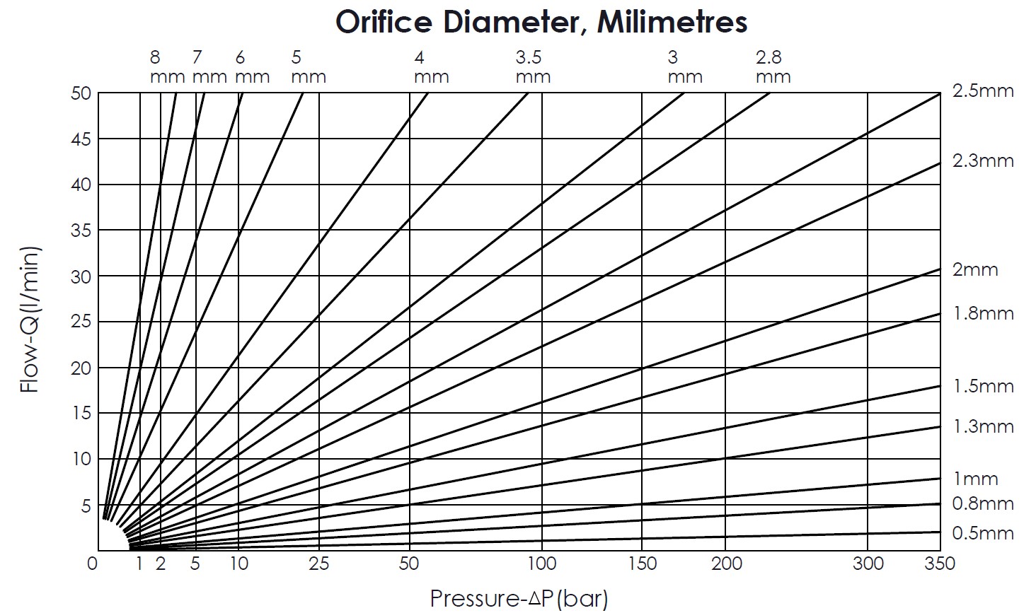
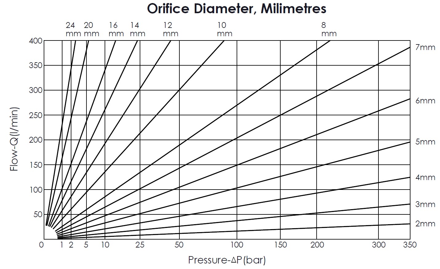
These charts are based on the formula:
Q=α x d2 x √ΔP
Where:
Q= Flow (LPM)
α= Orifice Cofficient (0.4212)
d= Orifice diameter (mm)
ΔP= Pressure Drop (bar)
NO allowance has been made for viscosity effects, or regain of pressure downstream.
PDF Download
Related information
- ホーム
- 技術リソース
- Technical Information
- Orifice vs. Pressure Drop Curves Chart